Introduction
In manufacturing, precision is non-negotiable. While software, CNC controllers, and cutting tools often get the spotlight, the foundation of precision lies in something more mechanical: workholding. At the heart of this lies the self-centering vise, a deceptively simple but technologically elegant device.
This article takes a deep engineering dive into the mechanics of self-centering vises, exploring how they work, what makes them different, and why they are the backbone of reliable, repeatable machining.
The Physics of Clamping
Any vise serves one main function: hold the workpiece firmly in place against machining forces. Machining generates cutting forces in multiple directions, often exceeding hundreds of kilograms. If the workpiece slips, even by microns, the result can be catastrophic—scrapped parts, broken tools, or even damaged machines.
The challenge is to create a high fixturing clamps force with minimal deformation. Traditional vises achieve this through screw-driven jaws, but they often sacrifice symmetry and repeatability.
The Self-Centering Principle
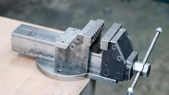
A self-centering vise solves this by using a synchronous mechanism. The jaws move in opposite directions at the same rate, ensuring the workpiece is automatically aligned to the vise’s centerline.
Two common mechanisms are used:
- Rack and Pinion System
- Both jaws are connected by a gear system. Turning the screw rotates a pinion, which drives two racks in opposite directions.
- Perfect symmetry is maintained.
- Both jaws are connected by a gear system. Turning the screw rotates a pinion, which drives two racks in opposite directions.
- Leadscrew and Nut System
- A central leadscrew with opposing threads moves two nuts (and jaws) toward or away from the center.
- This design is compact and commonly used in precision vises.
- A central leadscrew with opposing threads moves two nuts (and jaws) toward or away from the center.
Benefits from an Engineering Standpoint
- Geometric Symmetry: By definition, the jaws move equally, eliminating operator-dependent alignment.
- Load Distribution: The forces applied are balanced across the workpiece, minimizing distortion.
- Reduced Setup Tolerances: Parts are automatically positioned relative to the machine’s axis.
Key Engineering Considerations
- Clamping Force
Engineers must calculate clamping force requirements based on material hardness, tool engagement, and cutting parameters. Too little force risks slippage; too much risks deforming delicate parts. - Jaw Material
- Hardened steel for durability.
- Aluminum or polymer inserts for delicate surfaces.
- Quick-change jaws for high-mix environments.
- Hardened steel for durability.
- Stiffness & Rigidity
The vise body must resist deflection under load. Finite Element Analysis (FEA) is often used in design. - Thermal Stability
In long machining cycles, thermal expansion can alter alignment. High-grade alloys and coatings help mitigate this.
Failure Modes and Engineering Solutions
- Backlash in Gear Systems: Leads to misalignment → solved with preloaded gears.
- Wear of Leadscrew Threads: Reduces repeatability → solved with hardened materials and lubrication channels.
- Chip Ingress: Chips clogging the mechanism → solved with sealed housings and wipers.
Advanced Engineering Integrations
- Force Sensors: Embedding load cells in jaws to measure real-time clamping force.
- Automation Interfaces: Pneumatic or hydraulic 5th axis vises for robotic systems.
- Digital Twins: Simulating clamping forces and deformation before machining begins.
Conclusion
The self-centering vise is a marvel of mechanical design—simple in concept, yet sophisticated in execution. For engineers, understanding its inner workings means not only appreciating the elegance of the mechanism but also ensuring optimal performance in real-world cnc with 4th axis environments.
In the era of Industry 4.0, the self-centering vise is no longer “just a clamp”—it is a precision engineering tool that ensures machines deliver on their promise of accuracy, consistency, and efficiency.